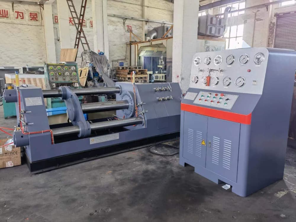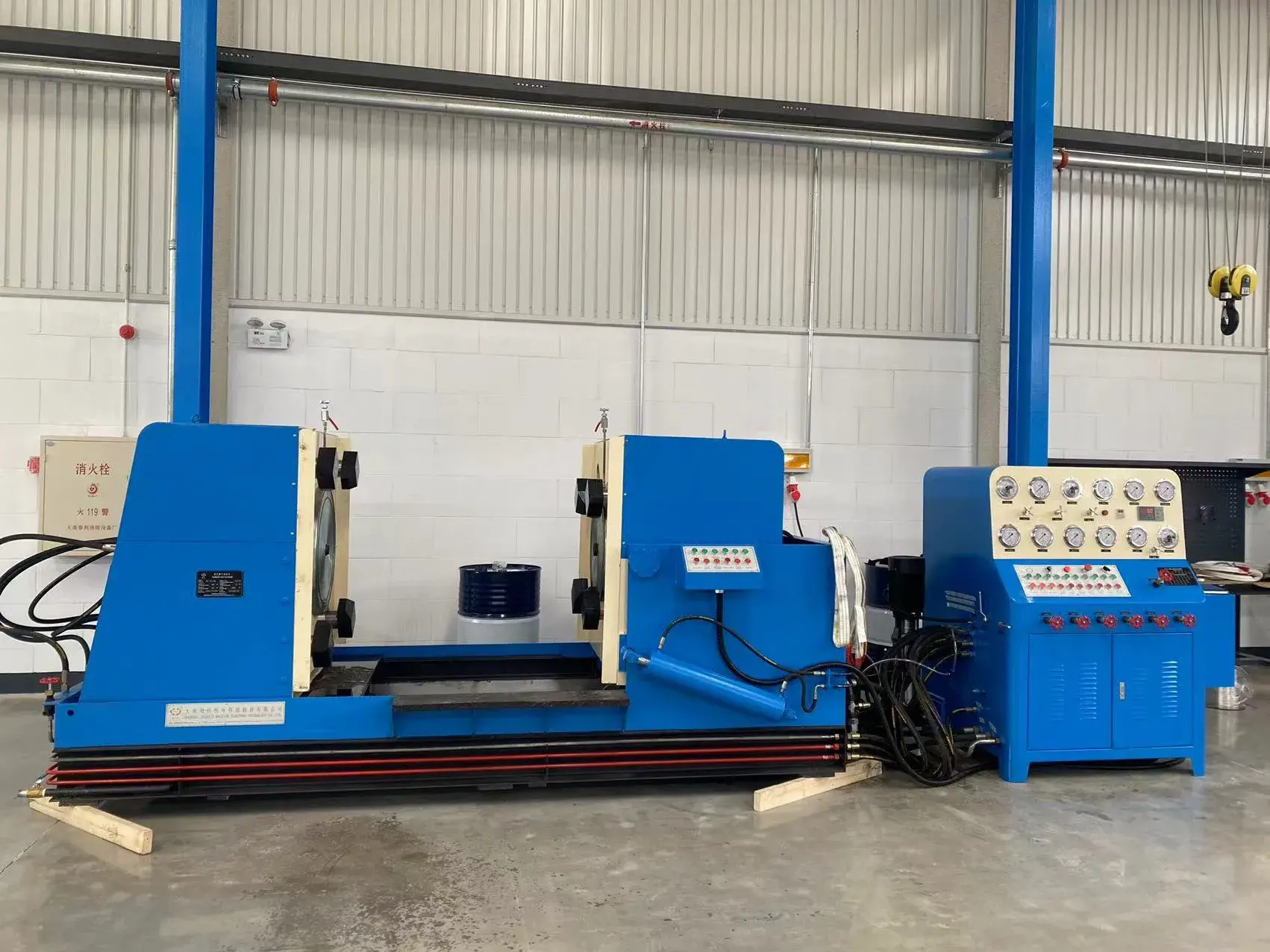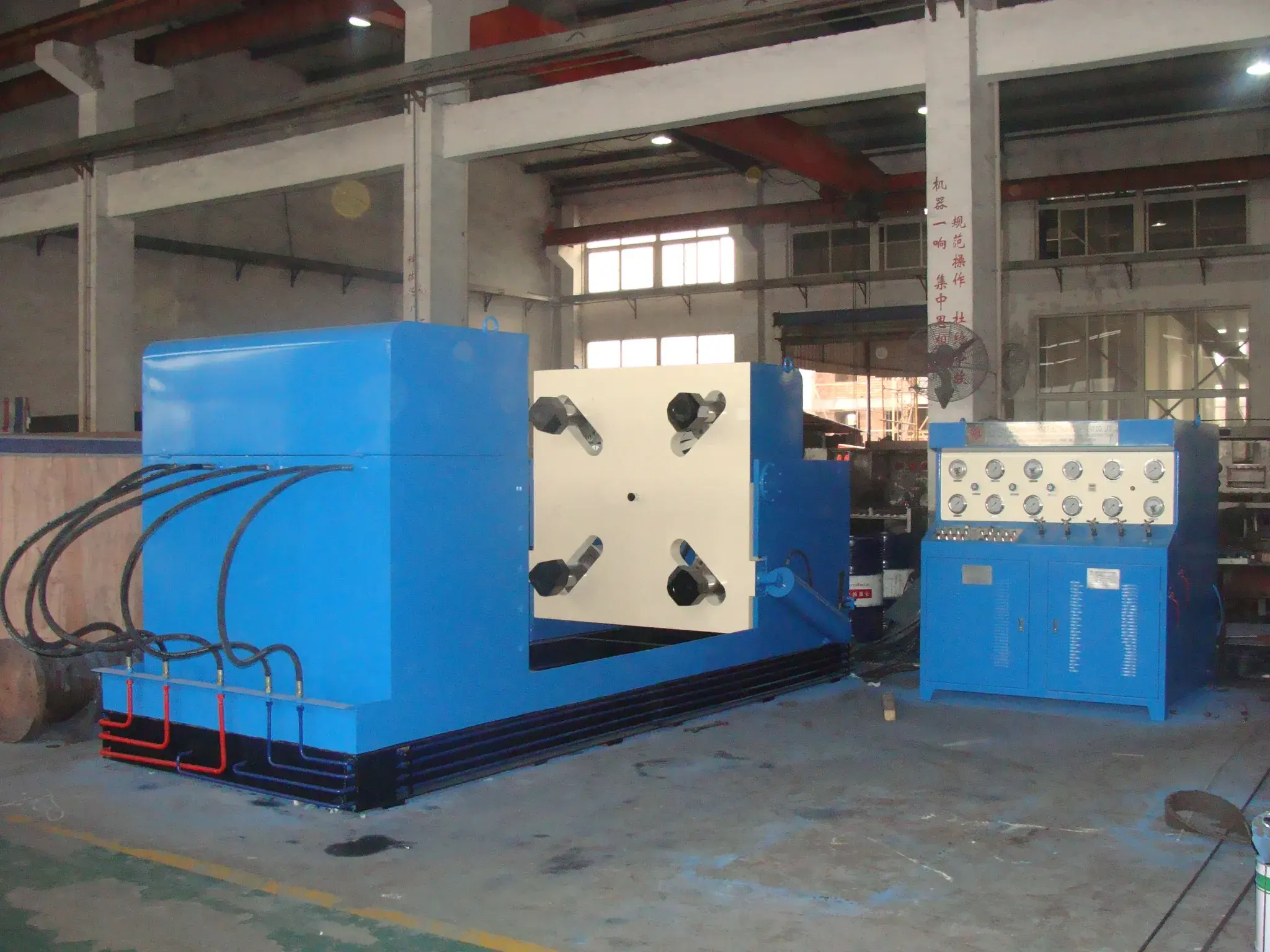
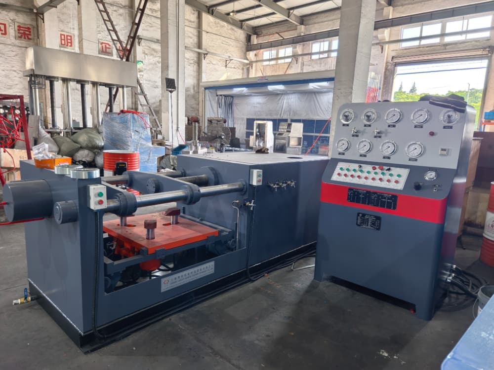
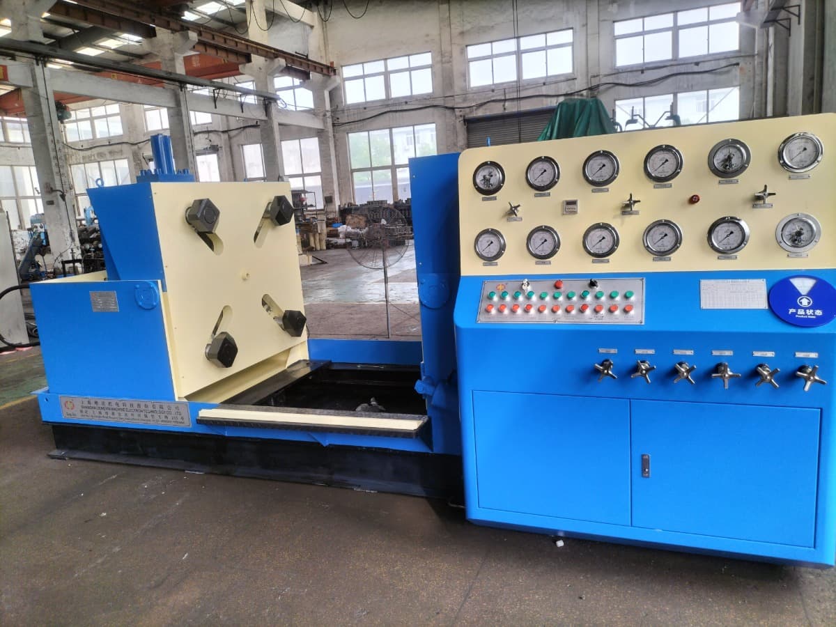
The hydraulic pressure holding valve test bench has two workbenches on the left and right, each equipped with a movable pressure claw clamping mechanism that can synchronously adjust the position of the pressure claw according to the flange size of the valve. The left workbench can be horizontally moved to accommodate the structural length of valves of different specifications and pressure levels, while the right workbench can be flipped 90 ° to facilitate leakage detection during single-sided sealing testing of valves.
The high-pressure hydraulic pressure required for the clamping force of the pressure claw is increased by the hydraulic system of the equipment itself. The tested water pressure system consists of a high flow low-pressure water pump and a low flow high-pressure water pump, as well as pipelines and control valves. When testing the valve, start a high flow low-pressure water pump to fill the valve chamber with the test medium. After the low-pressure water is filled, the system automatically starts the high-pressure water pump to input high-pressure water into the valve body. When the pressure of the test medium reaches the pre-set pressure, the high-pressure water pump automatically stops, and the system automatically enters the pressure holding timer state (the pressure holding time is set by the operator). When the pressure holding timer ends, the pressure holding timer end indicator light will light up, and the buzzer will sound to prompt;
◆It is suitable to have a shell test, closure test and back seal test for flanged end valves;
◆No external force affects a testing valve as clamp hold flange
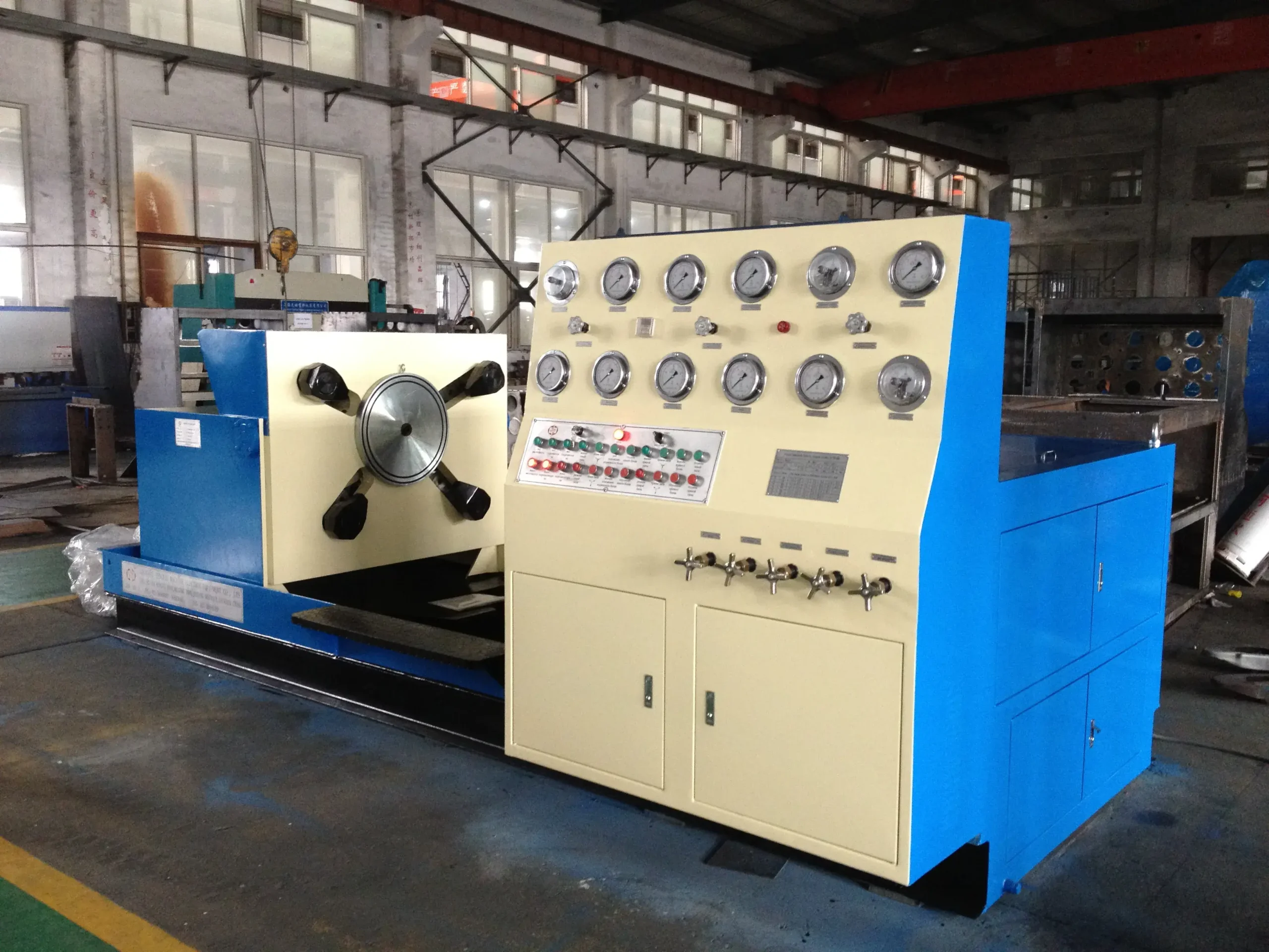
◆Valve can be turned to 90°to have a test(2 turning tables on option) so that it is convenient to carry out air seal test;
◆Test medium is water or air(6 bar gas source supplied by customer,test medium water can be recycling), can bechanged over by pipeline control valve;
◆Equipped LP water filling、 HP water filling and pressure-keeping & timing auto-control system;
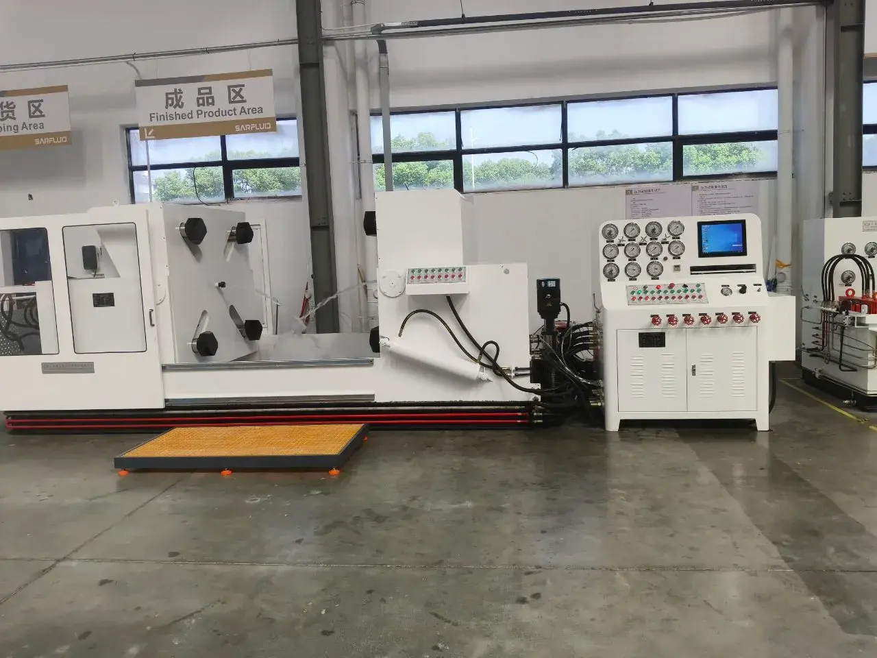
◆Equipped automatic oil pressure discharge system, when being ready state, system discharge automatically, whenworking, system return to normal status to effectively reduce oil temperature, elongate life of the test bench andsave energy:
◆Hydraulic clamping has safety interlock with water pressure discharge;
◆Customer can choose the functions as followed: Double turn over;Safety door; Touch screen monitoringsystem;One key automatic monitor system(touch screen computer+ PLC)
| Model specification | YFB-/※100 | YFB-/※200 | YFB-/※300 | YFB-/※400 | YFB-/※500 | YFB-/※600 | YFB-/※800 | YFB-/※1000 | YFB-/※1200 | |
|---|---|---|---|---|---|---|---|---|---|---|
| Test range between DN and PN | DN/mm Nominal diameter | 15 – 100 | 50 – 200 | 80 – 300 | 200 – 400 | 250 – 500 | 300 – 600 | 400 – 800 | 500 – 1000 | 600 – 1200 |
| PN/MPa Nominal pressure | 1.6 – 43.0 | 1.6 – 43.0 | 1.6 – 43.0 | 1.6 – 16.0 | 1.6 – 16.0 | 1.6 – 16.0 | 1.6 – 16.0 | 1.6 – 16.0 | 1.6 – 11.0 | |
| Valve face-to-face dimension | The min valve face-to-face dimension | 108 | 178 | 203 | 292 | 330 | 356 | 406 | 457 | 508 |
| The max valve face-to-face dimension | 432 | 597 | 673 | 838 | 991 | 1143 | 1524 | 1727 | 1981 | |
| Range between flange diameter and thickness | Min flange diameter/thickness | 90 / 10 | 150 / 16 | 190 / 19 | 345 / 29 | 405 / 31 | 485 / 32 | 600 / 37 | 700 / 43 | 815 / 48 |
| Max flange diameter/thickness | 275 / 58 | 380 / 66 | 520 / 75 | 650 / 74 | 775 / 77 | 915 / 93 | 1149 / 109 | 1289 / 115 | 1511 / 121 | |
| Blind flange spacing | Min.space between mm | 90 | 160 | 185 | 270 | 310 | 340 | 390 | 440 | 490 |
| Max.space between mm | 620 | 800 | 1000 | 1150 | 1320 | 1420 | 2100 | 2250 | 2500 | |
| Hydraulic system | Oil pump pressure MPa | 6.3 | ||||||||
| Displacement ml /r | 6.3 | 16 | 25 | 25 | 40 | 40 | 63 | 63 | 80 | |
| Boosting MPa | ≤31.5 | |||||||||
| Pressure adjusting range MPa | ≤6.3 | |||||||||
| Power | Voltage V / Frequency Hz | Customer local voltage | ||||||||
| Motor | Power kW / Pole P | 1.5 / 4 | 2.2 / 6 | 3 / 6 | 3 / 6 | 5.5 / 6 | 5.5 / 6 | 7.5 / 6 | 7.5 / 6 | 11 / 6 |
| Overall size | length mm(L) | 2550 | 2820 | 3100 | 3350 | 3750 | 3900 | 5200 | 5500 | 6000 |
| width mm(W) | 1230 | 1400 | 1510 | 1750 | 1800 | 1900 | 2400 | 2500 | 3000 | |
| height mm(H) | 1200 | 1300 | 1350 | 1450 | 1500 | 1650 | 2000 | 2200 | 2300 | |
| Weight(≈)kg | YFB-/**※※ | 1980 | 2400 | 3000 | 4400 | 5000 | 5600 | 8000 | 12000 | 14000 |
.jpg)