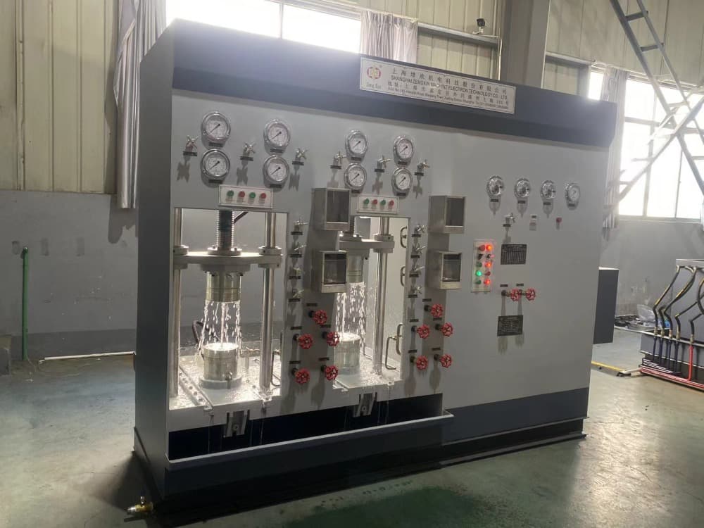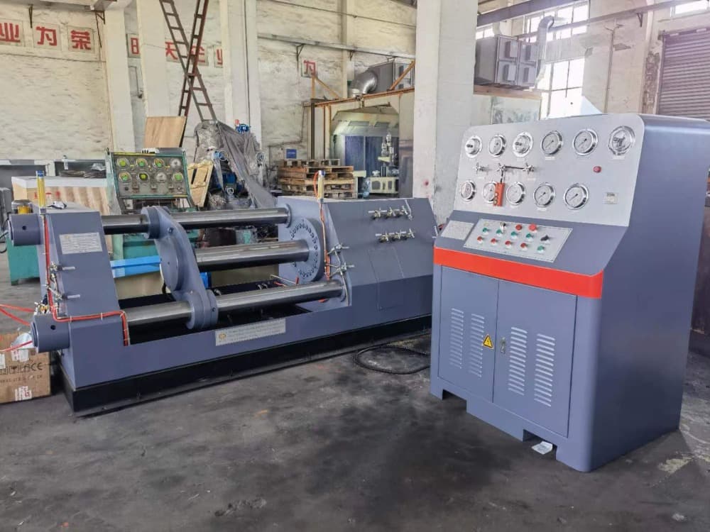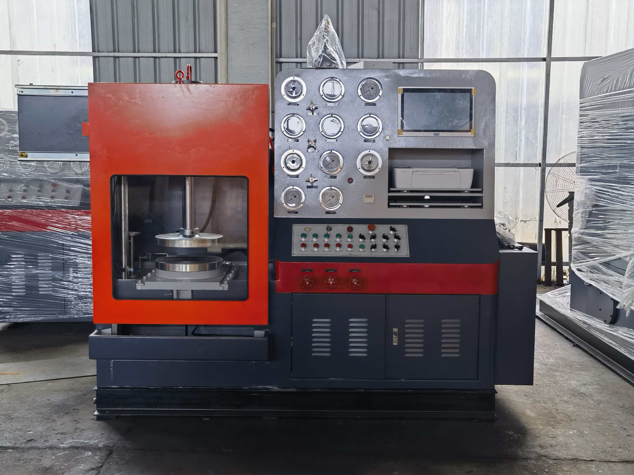
The core of the device is the transmission of mechanical force in the vertical direction. During operation, the high-strength screw located above the equipment rotates under the drive of the driving device motor, pushing the upper sealing pressure plate to move vertically downward. The tested valve is placed horizontally on the lower sealing seat, and the downward pressure generated by the screw acts on the upper flange of the valve through the upper pressure plate, tightly pressing it down on the lower sealing seat. The sealing elements on the upper and lower pressure plates deform under pressure, forming axial seals on the flanges at both ends of the valve, thus creating conditions for subsequent pressure testing.
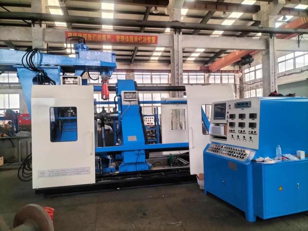
Simple structure, sturdy and durable: pure mechanical transmission, extremely low failure rate, almost maintenance free, long service life.
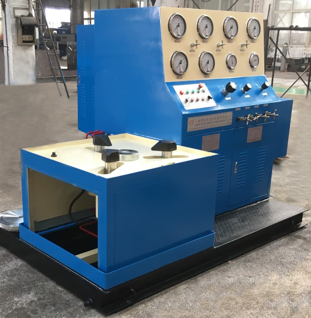
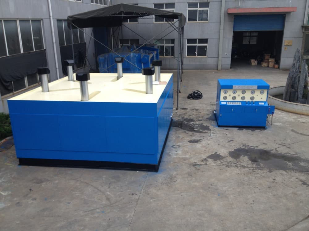
Small footprint and convenient operation: the vertical design saves valuable ground space; The valve is placed horizontally, and the clamping height conforms to ergonomics, making loading and unloading easy.
Extremely low investment and maintenance costs: no need for hydraulic systems, no oil leakage troubles, initial purchase cost and long-term maintenance cost are much lower than hydraulic equipment.
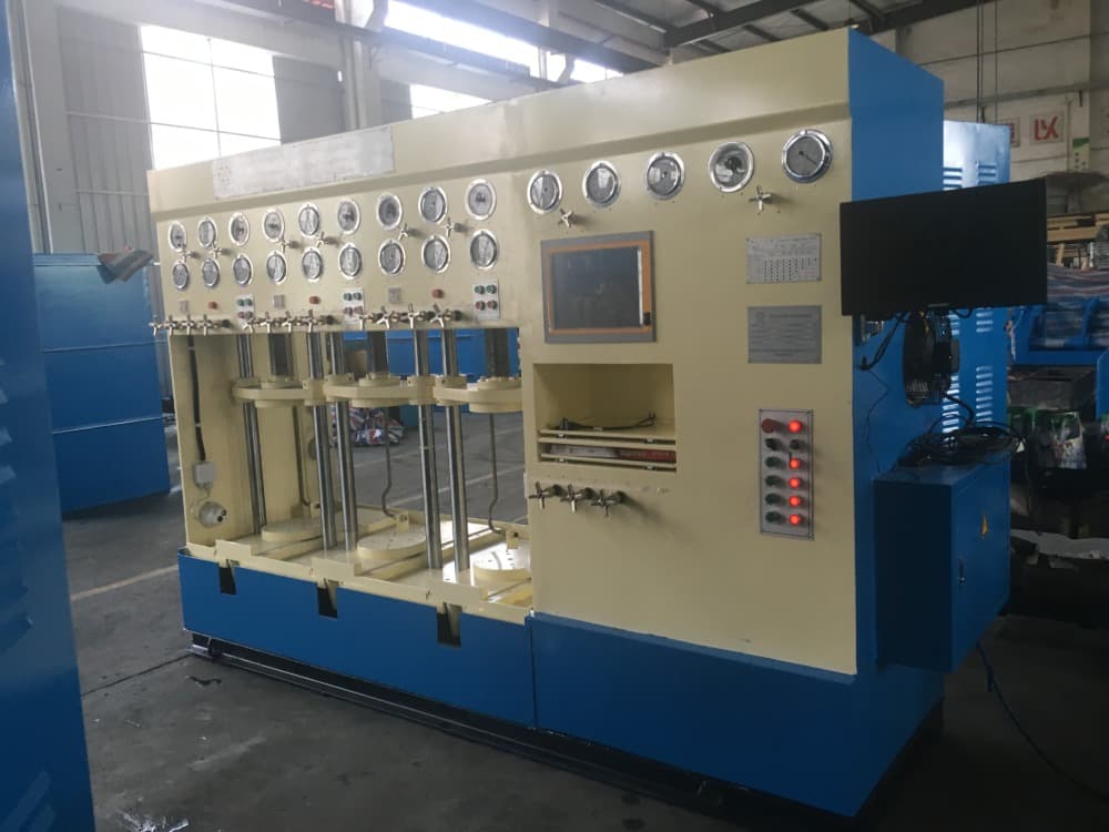
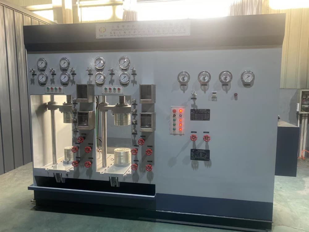
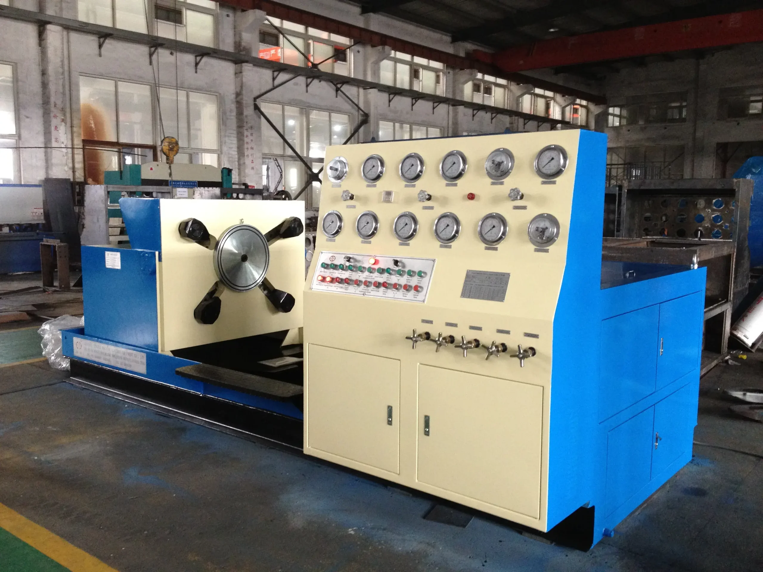
◆It is specially suitable for have a test for small sized flanged end valves, welded end or threaded valves;The upper pressing device has hydraulic driving and screw driving type;
◆An control system controls 1-6 valve test stations(on customer request);
◆It is equipped a claw press device and claw hold device and has wide suitability;
◆A top beam can be turned over 90°and the work table is fully open so that it is easy to operate;Test medium is water or air(6 bar gas source supplied by customer,test medium water can be recycling), can bechanged over by pipeline control valve;
◆Equipped LP water filling、 HP water filling and pressure-keeping & timing auto-control system;
◆Equipped automatic oil pressure discharge system, when being ready state, system discharge automatically, whenworking, system return to normal status to effectively reduce oil temperature, elongate life of the test bench andsave energy;
◆Hydraulic or screw clamping、 pressing device has safety interlock with water pressure discharge;
◆Customer can choose the functions as followed:Touch screen computer monitoring system;Safety door;Multi-station.
| Model specification | YFB-LY/※100
YFB-LL/※100 |
YFB-LY/※200
YFB-LL/※200 |
YFB-LY/※300
YFB-LL/※300 |
|
|---|---|---|---|---|
| Test range between DN and PN | DN/mm Nominal diameter | 15 - 100 | 50 - 200 | 80 - 300 |
| PN/Mpa Nominal pressure | 1.6 - 32.0 | 1.6 - 32.0 | 1.6 - 32.0 | |
| Valve face-to-face dimension | The min. valve face-to-face dimension/ mm | 108 | 178 | 203 |
| The max. valve face-to-face dimension/ mm | 432 | 597 | 648 | |
| Range between flange diameter and thickness | Min flange diameter/thickness/ mm | 90 / 10 | 150 / 16 | 190 / 19 |
| Max flange diameter/thickness/ mm | 275 / 51 | 380 / 58 | 520 / 65 | |
| Blind flange spacing | Min. space between/ mm | 95 | 165 | 190 |
| Max. space between/ mm | 490 | 650 | 750 | |
| Hydraulic system | Oil pump pressure/MPa | 6.3 | ||
| Displacement ml /r | 6.3 | 16 | 25 | |
| Boosting/MPa | ≤ 31.5 | |||
| Pressure adjusting range/MPa | ≤ 6.3 | |||
| Power | Voltage V/Frequency Hz | Customer local voltage | ||
| Motor |
Power kW /Pole P
|
1.5 / 4 | 2.2 / 6 | 3 / 6 |
| Overall size | length/ mm(L) | 1750 | 1850 | 2050 |
| width/ mm(W) | 800 | 1100 | 1100 | |
| height/ mm(H) | 1850 | 1850 | 1850 | |
| Weight | kg | 1500 | 2000 | 2500 |