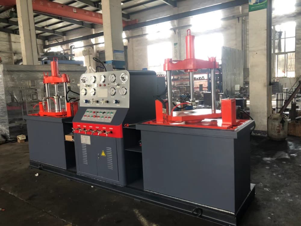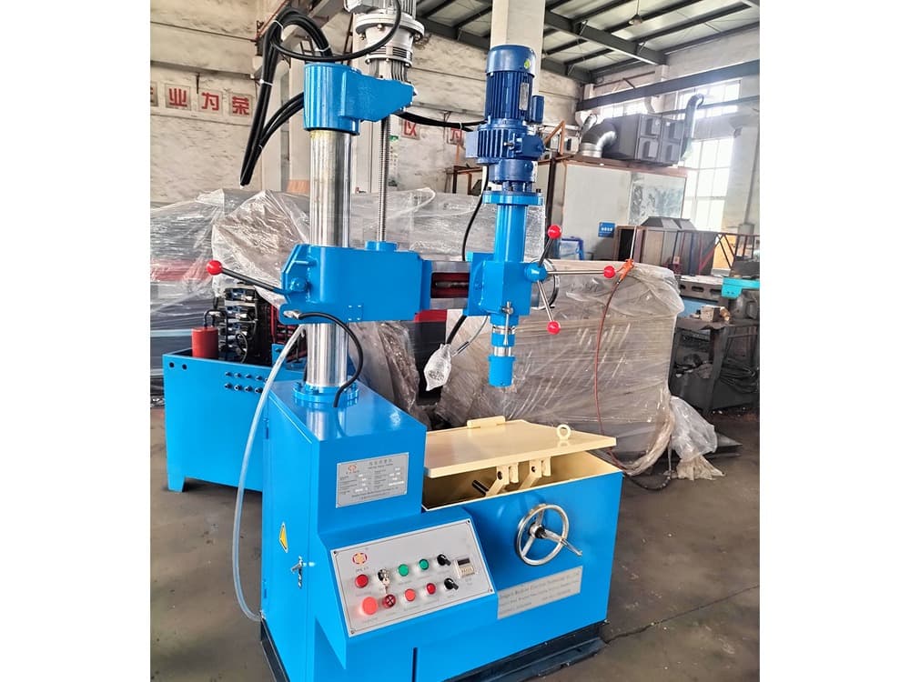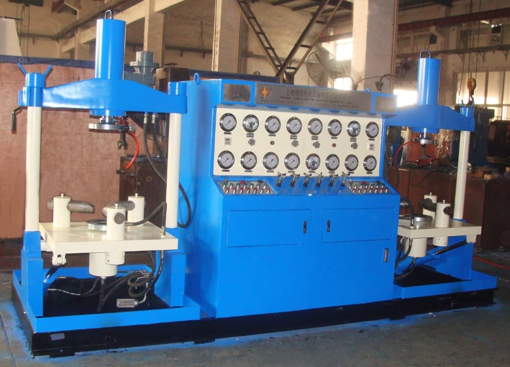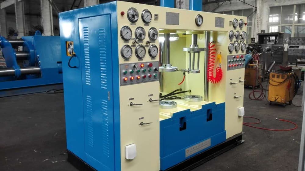
The hydraulic cylinder top pressure valve test bench is a universal, efficient, and powerful valve testing equipment. The core design concept is to use the axial thrust generated by the hydraulic cylinder to directly drive the end face sealing pressure plate or blind plate, and to compress and seal the tested valve between its end flanges, thereby conducting the valve’s shell strength test and sealing performance test. This device has become the mainstream choice for product quality inspection and certification in valve manufacturing, pressure vessels, and various industrial fields due to its strong clamping force, wide applicability, and excellent sealing effect.
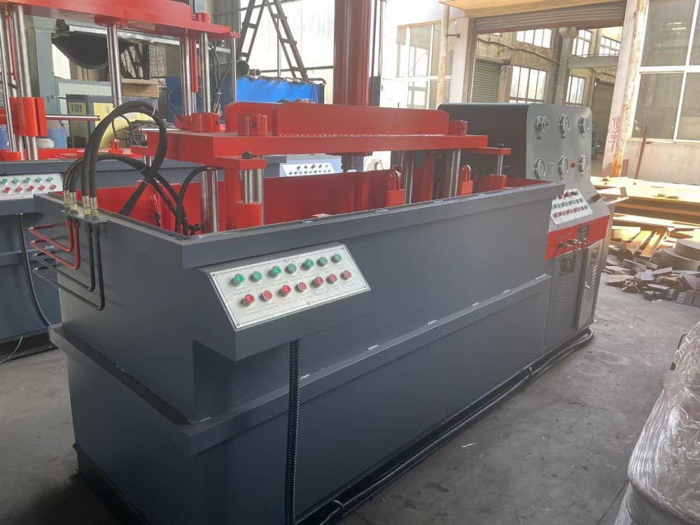
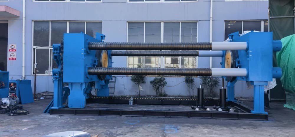
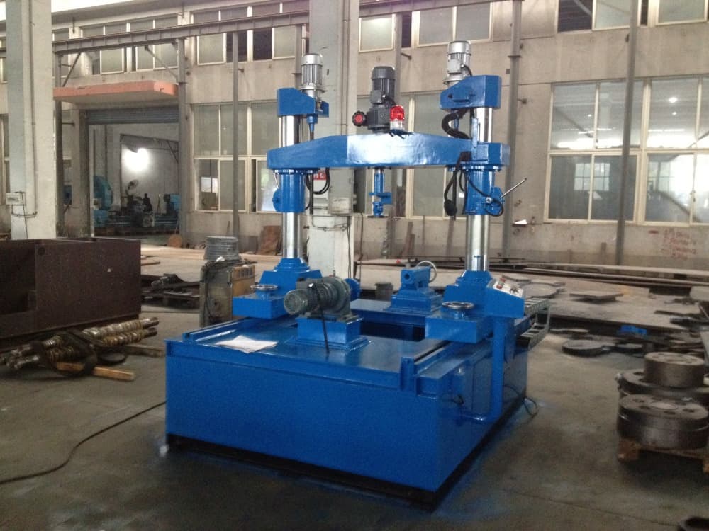
Made of high-strength box beams or high-quality thick steel plates welded together, the structure is stable and can withstand the huge pushing force of the oil cylinder and the high-pressure reaction force generated during testing, ensuring long-term use without deformation.
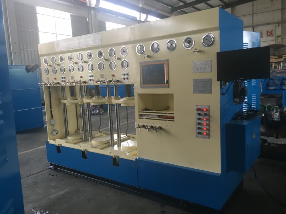
Usually a horizontal structure, providing open operating space
◆The test bench is made up of 2 parts: operation control table and clamping pressure test device, clamping pressuretest device can all be submerged under water, which is up or down by oil pressure;
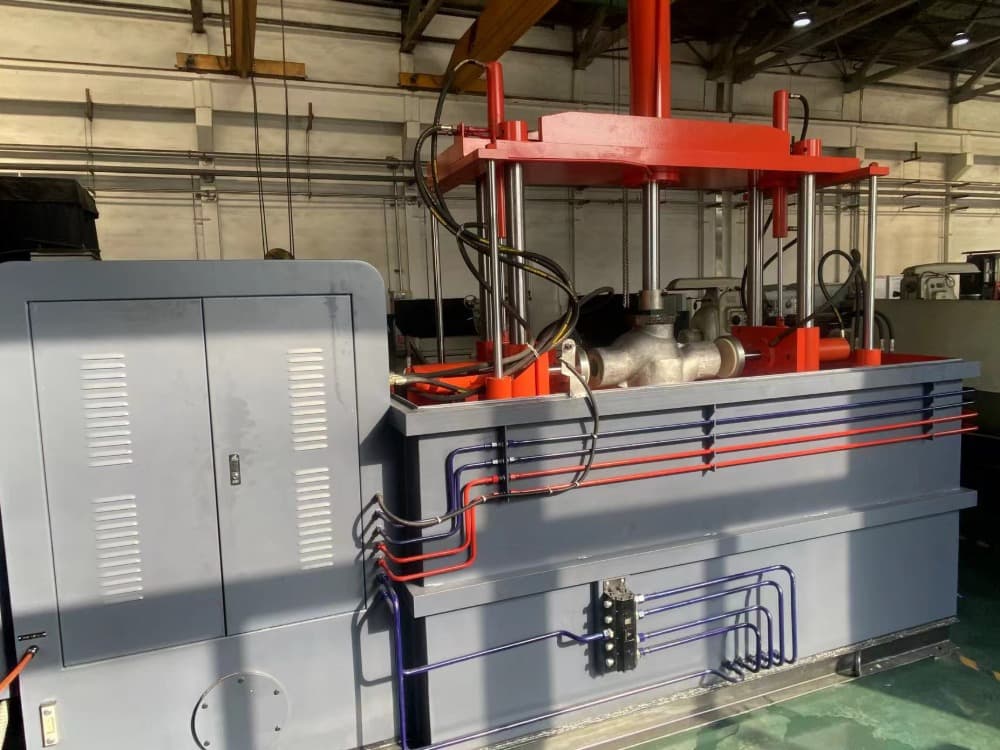
◆Submerged type valve test bench is suitable to have a test for flanged end valves;Submerged top pressure type issuitable to have a test for flanged end、 welded groove or inner tunnel sealing type valves;
◆Test medium is water or air(6 bar gas source supplied by customer,test medium water can be recycling), can be changed over by pipeline control valve;
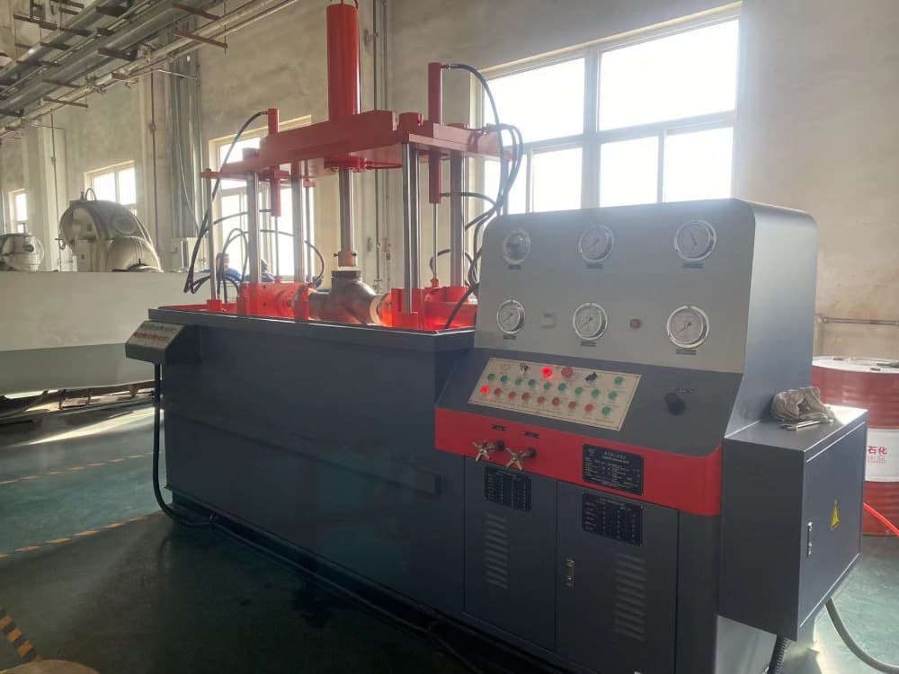
◆Equipped LP water filling、 HP water filling and pressure-keeping & timing auto-control system;
◆Equipped automatic oil pressure discharge system, when being ready state, system discharge automatically, whenworking, system return to normal status to effectively reduce oil temperature, elongate life of the test bench andsave energy;
◆Hydraulic or screw clamping、 pressing device has safety interlock with water pressure discharge;Customer can choose the functions as followed: Double turn over; Touch screen monitoring system.
| Model specification | YFB-QS/※100 | YFB-QS/※200 | YFB-QS/※300 | YFB-QS/※400 | YFB-QS/※500 | YFB-QS/※600 | YFB-QS/※800 | |
|---|---|---|---|---|---|---|---|---|
| Test range between DN and PN |
DN/mm Nominal diameter
|
15 – 100 | 50 – 200 | 80 – 300 | 200 – 400 | 250 – 500 | 300 – 600 | 400 – 800 |
| PN/MPa Nominal pressure | 1.6 – 43.0 | 1.6 – 43.0 | 1.6 – 43.0 | 1.6 – 16.0 | 1.6 – 16.0 | 1.6 – 16.0 | 1.6 – 16.0 | |
| Valve face-to-face dimension | The min valve face-to-face dimension/mm | 108 | 178 | 203 | 292 | 330 | 356 | 406 |
| The max valve face-to-face dimension/mm | 432 | 597 | 673 | 838 | 991 | 1143 | 1524 | |
| Range between flange diameter and thickness | Min flange diameter/thickness/mm | 90 / 10 | 150 / 16 | 190 / 19 | 345 / 29 | 405 / 31 | 485 / 32 | 600 / 37 |
| Max flange diameter/thickness/mm | 275 / 58 | 380 / 66 | 520 / 75 | 650 / 74 | 775 / 77 | 915 / 93 | 1149 / 109 | |
| Blind flange spacing | Min.space between/mm | 90 | 160 | 185 | 270 | 310 | 340 | 390 |
| Max.space between/mm | 620 | 800 | 1000 | 1150 | 1320 | 1420 | 2100 | |
| Hydraulic system | Oil pump pressure/MPa | 6.3 | ||||||
| Displacement/ml /r | 6.3 | 16 | 25 | 25 | 40 | 40 | 63 | |
| Boosting/MPa | ≤31.5 | |||||||
| Pressure adjusting range/MPa | ≤6.3 | |||||||
| Power | Voltage/Frequency/Hz | Customer local voltage | ||||||
| Motor | Power kW/Pole P | 1.5 / 4 | 2.2 / 6 | 3 / 6 | 3 / 6 | 5.5 / 6 | 5.5 / 6 | 7.5 / 6 |
| Overall size | length/ mm(L) | 2550 | 2820 | 3100 | 3350 | 3750 | 3900 | 5200 |
| width/ mm(W) | 1230 | 1400 | 1510 | 1750 | 1800 | 1900 | 2400 | |
| height/ mm(H) | 1200 | 1300 | 1350 | 1450 | 1500 | 1650 | 2000 | |
| YFB-QS/※※Water tank size | length/ mm(L) | 2200 | 2580 | 2800 | 3100 | 3300 | 3600 | 4700 |
| width/ mm(W) | 750 | 850 | 1130 | 1300 | 1500 | 1600 | 2200 | |
| height/ mm(H) | 1060 | 1650 | 2000 | 2300 | 2500 | 2600 | 2660 | |
| Weight(≈)kg | YFB-QS/※※ | 2500 | 3600 | 4800 | 7200 | 8000 | 9000 | 13000 |