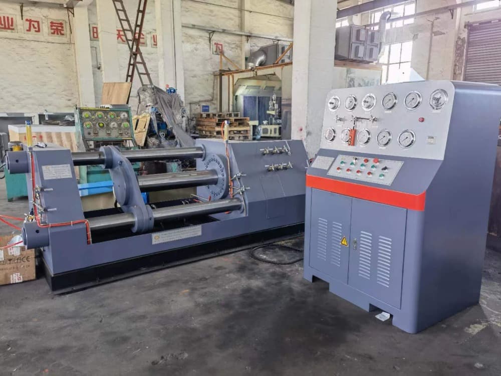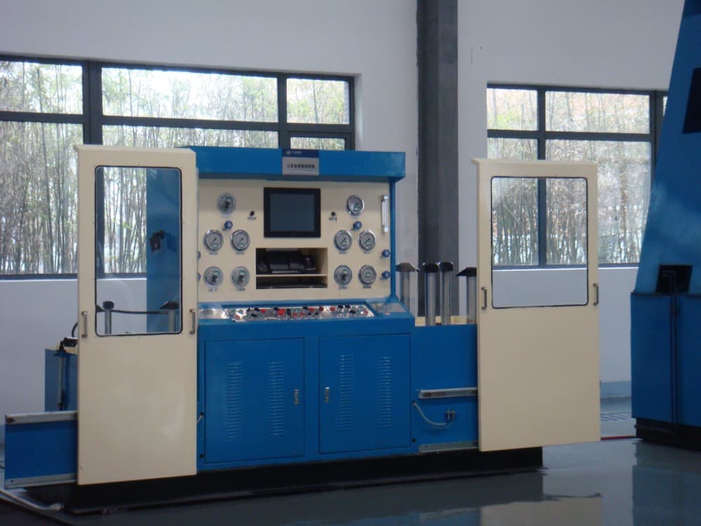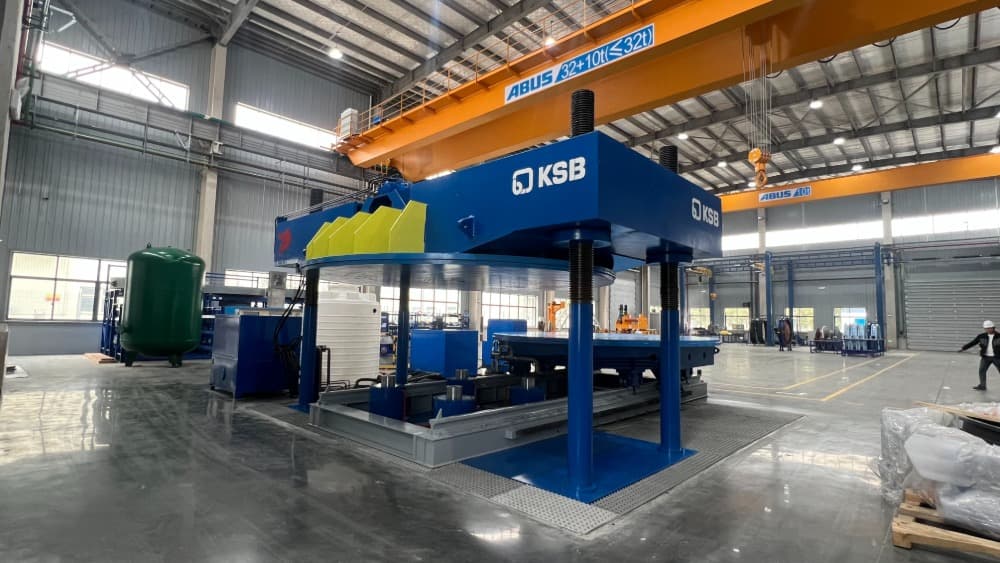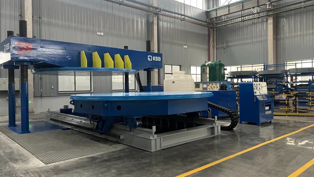
The butterfly valve testing equipment mainly consists of hydraulic system, mechanical system, electrical system, and pipeline system. It can perform shell and seal tests on valves under a large range of valve specifications and pressure, respectively. This equipment integrates mechanical transmission, hydraulic transmission, and electrical automatic control, with complete functions, easy and flexible operation, stable and reliable performance, high degree of automation, greatly improving production efficiency and reducing labor intensity. It is an ideal preferred equipment for valve manufacturing, use, and maintenance enterprises.
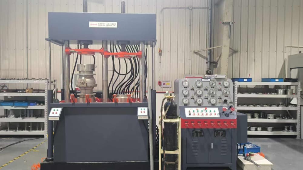
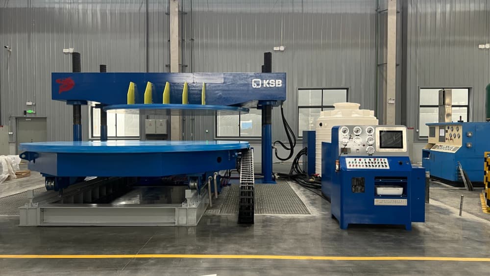
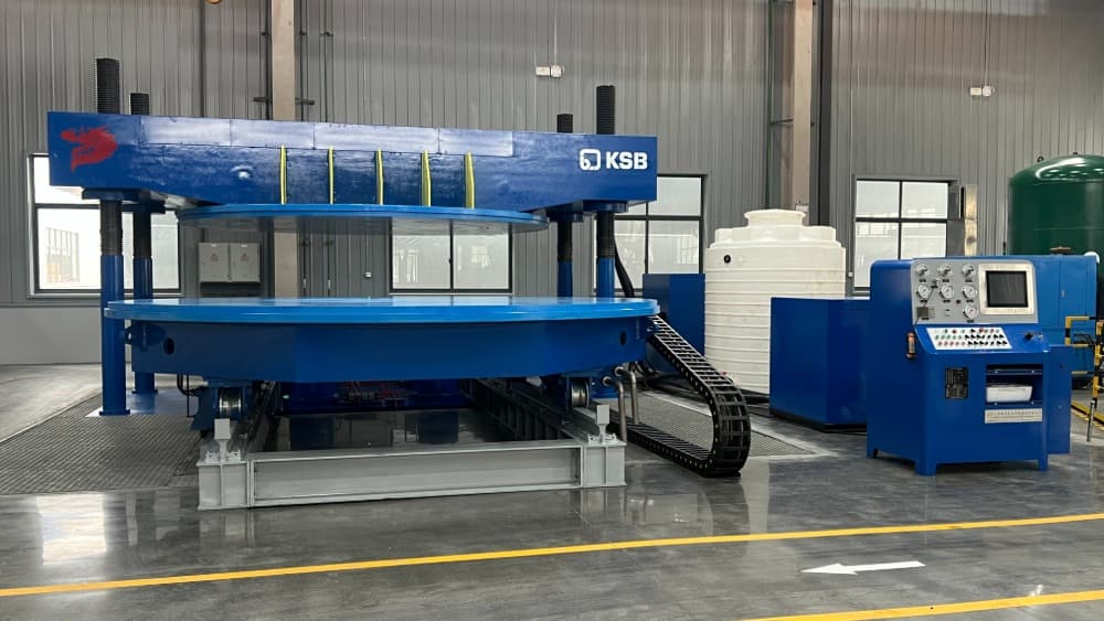
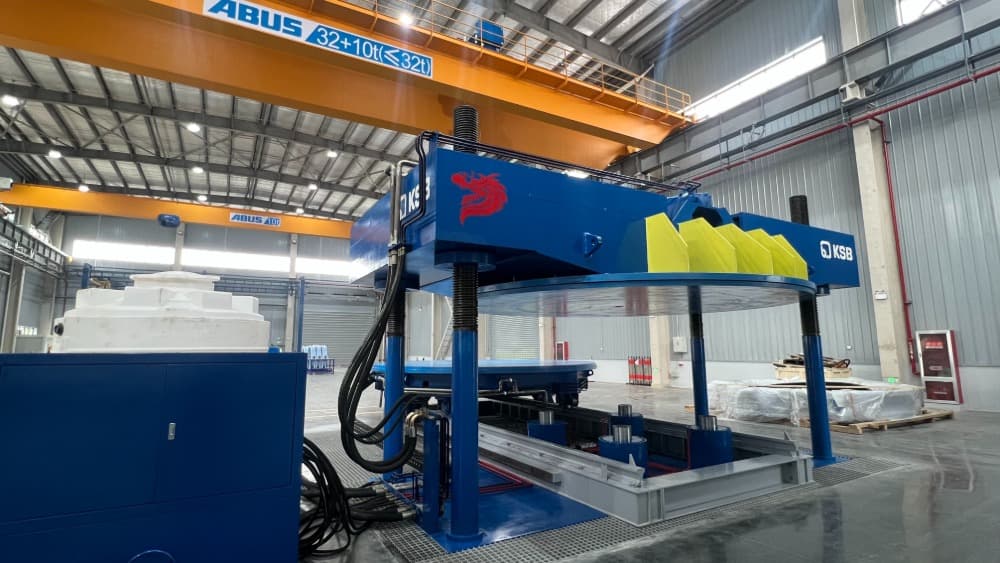
The mechanical system of the test bench consists of a main frame, a clamping worktable, and sealing blind plates corresponding to various butterfly valve diameters. The pressure test is conducted by positioning the valve flange end face and clamping the flange with a movable pressure claw. There is a movable pressure claw clamping mechanism on the work disk, which can synchronously adjust the position of the pressure claw according to the flange size of the valve. The high-pressure hydraulic pressure required for the clamping force of the pressure claw is increased by the hydraulic system of the equipment itself.
◆It is suitable to have a test for flanged end and wafer end butterfly valves;
◆The claws are simultanously moved or clamped;
◆There are single station and double stations on cutomer request;
◆Test medium is water or air(6 bar gas source supplied by customer,test medium water can be recycling), can bechanged over by pipeline control valve;
◆Equipped LP water filling、 HP water filling and pressure-keeping & timing auto-control system;
◆Equipped automatic oil pressure discharge system, when being ready state, system discharge automatically, whenworking, system return to normal status to effectively reduce oil temperature, elongate life of the test bench andsave energy;
◆Hydraulic clamping has safety interlock with water pressure discharge;
◆Customer can choose the functions as followed: Touch screen computer monitoring system; Double stations
| Model | YFB-DF/※300 | YFB-DF/(2)250/※500 | YFB-DF/(2)300/※800 | YFB-DF/(2)300/※800 | YFB-DF/(2)500/※1000 | YFB-DF/(2)600/※1200 | YFB-DF/(2)800/※1600 | YFB-DF/※2000 | YFB-DF/※2200 | YFB-DF/※2400 | YFB-DF/※3000 | YFB-DF/※3600 | |
|---|---|---|---|---|---|---|---|---|---|---|---|---|---|
| specification | DN
50-300 |
DN250-500
DN50-250 |
DN300-600
DN50-300 |
DN350-800
DN50-300 |
DN500-1000
DN250-500 |
DN700-1200
DN300-600 |
DN900-1600
DN350-800 |
DN1200
-2000 |
DN1400
-2200 |
DN1600
-2400 |
DN1600
-3000 |
DN1600
-3600 |
|
| Hydraulic system | Oil pump pressure/MPa | 6.3 | |||||||||||
|
Displacementml /r
|
16 | 25 | 25 | 25 | 40 | 40 | 40 | 63 | 63 | 63 | 80 | 80 | |
|
High pressure (Boosting)/MPa
|
≤31.5 | ||||||||||||
|
Pressure adjusting range/MPa
|
≤6.3 | ||||||||||||
| Power |
Voltage / Frequency
|
Customer local voltage | |||||||||||
|
Motor
|
Power kW / Pole P
|
2.2 / 6 | 3 / 6 | 3 / 6 | 3 / 6 | 5.5 / 6 | 5.5 / 6 | 5.5 / 6 | 7.5 / 6 | 7.5 / 6 | 7.5 / 6 | 11 / 6 | 11 / 6 |
| The min. valve flange(mm) | 150 | 150 / 395 | 150 / 445 | 150 / 505 | 395 / 670 | 445 / 895 | 505 / 1075 | 1405 | 1575 | 1790 | 1790 | 1790 | |
| The max. valve flange(mm) | 485 | 405 / 700 | 485 / 815 | 485 / 1060 | 700 / 1289 | 815 / 1485 | 1060 / 1915 | 2325 | 2475 | 2685 | 3405 | 3840 | |
| The max. distance between claw and work table(mm) | 370 | 370 / 550 | 370 / 620 | 370 / 637 | 550 / 1100 | 620 / 1225 | 637 / 1225 | 1225 | 1250 | 1250 | 1250 | 1250 | |
| Overall size | length L (mm) | 2000 | 3500 | 3500 | 3600 | 4150 | 4900 | 5200 | 4500 | 5000 | 5500 | 8400 | 10700 |
| width W (mm) | 1200 | 1350 | 1350 | 1500 | 1850 | 2200 | 2350 | 2750 | 3300 | 3600 | 6160 | 8200 | |
| height H (mm) | 1850 | 1980 | 1980 | 2050 | 2050 | 2050 | 2200 | 2200 | 2200 | 2200 | 3065 | 3100 | |
|
Weight ≈(kg) |
2000 | 4500 | 4500 | 6000 | 7500 | 8000 | 9800 | 9000 | 11500 | 13000 | 58000 | 70000 | |